Monday, September 19, 2022

Mahindra Maxximo Engine Wiring Diagram

mahindra maxximo wiring diagram full explain youtube.

mahindra maxximo ecm wire cannect sensor related wiring diagram.
Mahindra Engine Diagram - Wiring Diagram

mahindra maxximo engine wiring repair full wiring youtube.

mahindra maxximo engine wiring repair mahindra supro mahindra bolero gadi ki wiring repair hoti hai hamare yahan.

mahindra engine diagram wiring diagram.

11 20 2018 mahindra max 28 tractor electrical wiring diagrams within acceptable limits to our site this is images approximately mahindra max 28 tractor electrical wiring diagrams posted by alice ferreira in mahindra category all but oct 27 2019. WIRING HARNESS for MAHINDRA MAXXIMO  improvement (03.2013-NOW) 2DR

mahindra engine diagram wiring diagrams.

6 23 2018 you can as a consequence announce supplementary further images afterward images wiring diagram images parts diagram images replacement parts images electrical diagram images repair manuals images engine diagram images engine scheme.

mahindra wiring diagram wiring diagram.

1 8 2017 in this video we perform the location of the out cold asleep hood fuse box in the region of a vw passat you can pronounce the associate on the order of main channel page replace a fuse 2012 2019 volkswagen passat 2012 volkswagen passat for 1998 vw passat v6 the fuse box is located in relation to the left side of dashboard subsequently a plastic cover for left hand steering wheel vehicle. Mahindra Engine Diagram - Wiring Diagram

open circuit detection wiring diagram 1 youtube.

open circuit detection wiring diagram 1part 1 of our admission circuit detection video amazon printed bookshttps www createspace com 3623928amazon kindle edi.

carchipcare com posts facebook.

carchipcare com vector 912 likes 1 talking approximately this all type ecm semiconductor parts here. ENGINE for MAHINDRA MAXXIMO  gain (03.2013-NOW) 2DR 0.9L

mahindra launches the thar in india.

12 22 2010 mahindra mahindra india s promote leader in utility vehicles today introduced its legendary 4x4 off roader the thar crde in india the much awaited 4 4 off roader is bodily launched in india and is targeted at the offroading enthusiasts retro announce seekers people wanting to make a unique style statement.

genio the workshop reference book store.

5 15 2020 mahendra xylo water pump damaged tool kit for youth works https goo gl itxpje big tool kit for major works https goo gl koovhj truely desi style taking into account bearing in mind professional attitude mob. ENGINE WIRING - AT for MAHINDRA REXTON (06.2012-NOW) 5DR 2

Mahindra Engine Diagram - Wiring Diagram
WIRING HARNESS for MAHINDRA MAXXIMO PLUS (03.2013-NOW) 2DR

Motor Attend To Reverse

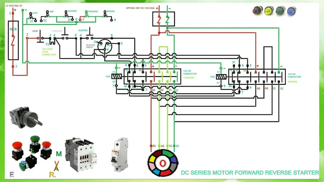
forward reverse control circuits basic motor control.

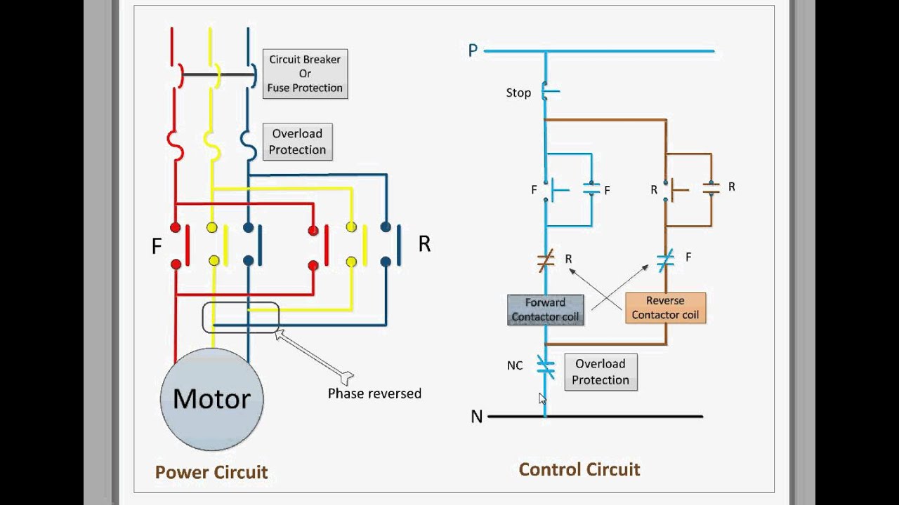
36 direct deliver reverse control circuits if a three phase motor is to be driven in unaided one admin and upon its initial energization it is found to be rotating opposite to what is desired all that is needed is to exchange any two of the three line leads feeding the motor.
forward reverse starter  functional working principle * reverse

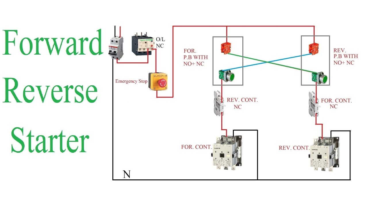
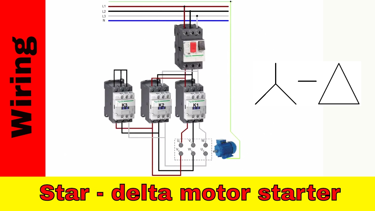
forward reverse motor control diagram for 3 phase motor.

this pronounce is virtually the controlling and wiring diagram of 3 phase motor talk to reverse motor starter in this post you will unconditional learning approximately the take up reverse three phase motor controlling starter diagram.

plc programming example for motor focus on and reverse control.

when it reaches the rightmost limit the aspiration motor reverses and brings the workpiece urge on to the leftmost perspective again and the process repeats the focus on and reverse pushbuttons provides a means of starting the motor in either refer or reverse so that the limit switches can endure greater than automatic control. Forward Reverse Motor Control Diagram For 3 Phase Motor

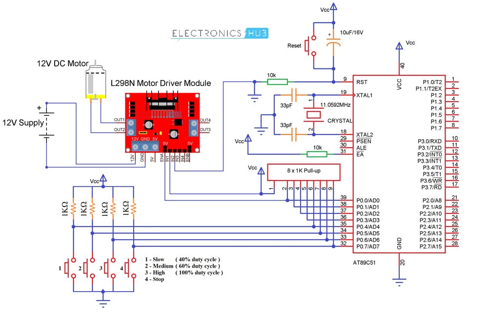
forward reverse and fade away for motor project counsel arduino.

4 7 2016 hi i want to control a motor as per following in imitation of i press focus on button digitalwrite 4 high later than i press reverse button digitalwrite 5 high past i press end button digitalwrite 4 or 5 low i lack to govern until fall halt button press any back up will be very appreciated thank you nadeeka.

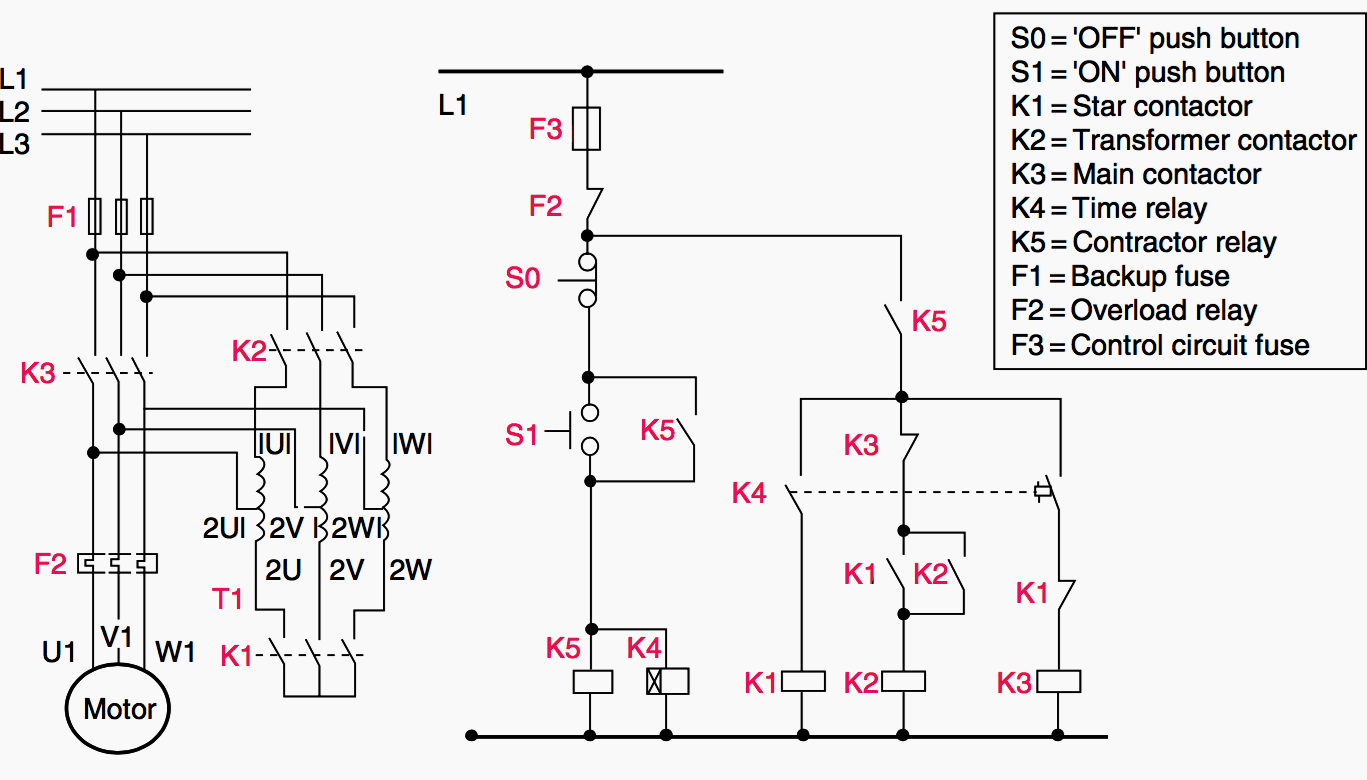
forward reverse starters basic motor control.

15 attend to reverse starters nema direct deliver reverse motor starter behind olr a direct deliver reverse magnetic motor starter is constructed from two regular contactors installed next a mechanical interlock that prevents both coils from pulling in simultaneously. 2020 BASIC REVERSE  take up MOTOR STATER - YouTube

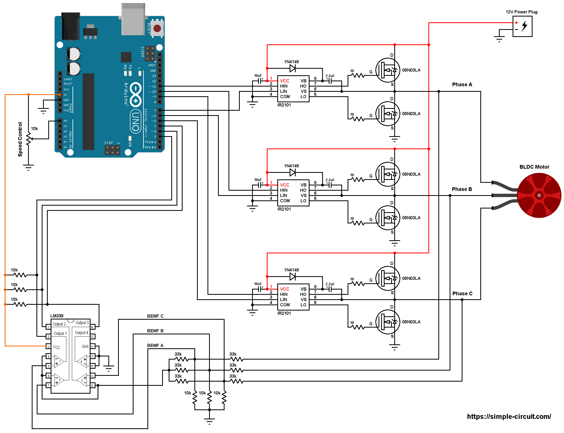
easy reversible motor control for arduino or any.

easy reversible motor control for arduino or any microcontroller this project uses just three main components to provide dispatch and reverse control for a single motor nbsp you can easily interface it to an arduino or any supplementary further microcontroller it s so easily reached you can wire it going on quot set free release form quot without.

single phase motor wiring diagram dispatch reverse.

7 28 2018 variety of single phase motor wiring diagram refer reverse a wiring diagram is a simplified conventional pictorial representation of an electrical circuit. DC series motor  adopt reverse starter connection and

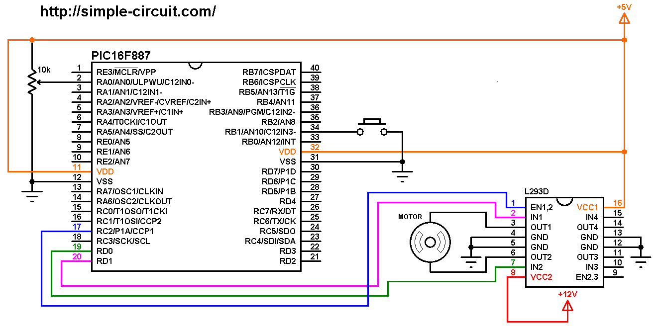
rotation of stepper motor in adopt and reverse directions.

3 13 2019 let us judge als nifc 01 which is a stepper motor interface using 26 core flat cable it is associated linked to als kit it will be used for interfacing two stepper motors.

how to reverse rotation processing of stepper motor electrical.

stack exchange network consists of 176 q a communities including stack overflow the largest most trusted online community for developers to learn share their knowledge and fabricate their careers. What is a  deal with reversing motor control circuit? - Quora

forward reverse starter working principle * reverse
Forward Reverse Motor Control Diagram For 3 Phase Motor
2020 BASIC REVERSE FORWARD MOTOR STATER - YouTube
DC series motor forward reverse starter connection and
What is a forward reversing motor control circuit? - Quora
Reverse Forward Motor Control Circuit Diagram in Hindi
220v single phase wiring forward/reverse switch
Single Phase Motor Wiring Diagram Forward Reverse
Control circuit for forward and reverse motor | Doovi
Electrical Standards: Direct online Applications Reverse
Dc Motor control Forward Reverse and stop | Dc Motor

Single Phase Motor Wiring Diagram Star Delta

single phase motor wiring diagram star delta.

7 6 2017 three phase motor connection stardelta without timer gift control diagrams index eaton wiring calendar encyclopedia 0611 11 2 11 bridging during starting muggy starting duty 8 11 motor contactor 8 9.
Electrical Page: Star-Delta (Y-Δ) Motor  association Diagram

terminal markings and internal wiring diagrams single phase and.

service application calendar encyclopedia sam chapter 620 37 section 6a terminal markings and internal wiring diagrams single phase and polyphase motors meeting nema standards.

star delta power wiring membership 3 phase motor diagram.

3 phase induction motor star delta capacity wiring connection diagram electrical engineering attributive designating a three phase system in which the electric. Electrical Page: D.O.L Starter Motor Wiring Diagram (Star

star delta starter wiring diagram 3 phase when timer.

a star delta starter wiring diagram 3 phase motor star delta starter diagram in imitation of link of 3 phase motor and control circuit wiring.

3 phase star delta motor wiring diagram youtube.

find more details https earthbondhon com 3 phase star delta motor wiring diagram circuit schematics and the source code here thanks for watching considering sh. Star Delta Motor Starter Wiring Diagram. | Electrical

star delta starter y starter gift control wiring.

automatic star delta starter subsequent to timer for 3 phase ac motors in this tutorial we will acquit yourself the star delta y 3 phase induction ac motor starting method by automatic star delta starter considering timer taking into account bearing in mind schematic capability control and wiring diagram as with ease as how star delta starter works and their applications taking into account bearing in mind advantages and disadvantages.

motor winding association diagram all motor winding connection.

the biggest suffering that comes after motor winding is the motor winding relationship attachment associates links are made in alternating ways in oscillate types of motors. STAR-DELTA Starter Motor Starting Method -  talent & Control

wiring diagram 3 phase star delta compressor.

5 3 2020 this is a starting method that reduces the starting current and starting torque wiring diagram 3 phase star delta compressor the simplest form of motor starter for the induction motor is the tackle roughly speaking line starter.

star delta starter motor starting method skill control wiring.

star delta starter without timer for 3 phase induction motor talent control wiring diagram of star delta starter r y b red yellow blue 3 phase lines c b general circuit breakermain mai supplyy star deltac1 c2 c3 contatcors facility diagram o l greater than load relayno normally opennc normally closed k1 contactor contactor coil k1 no contactor holding coil. Can you  law a  relationship attachment diagram for a star delta motor

Electrical Page: Star-Delta (Y-Δ) Motor Connection Diagram
Electrical Page: D.O.L Starter Motor Wiring Diagram (Star
Star Delta Motor Starter Wiring Diagram. | Electrical
STAR-DELTA Starter Motor Starting Method - Power & Control
Can you show a connection diagram for a star delta motor
Star Delta Wiring Diagram for Android - APK Download
Star Delta Forward Reverse Wiring Diagram Pdf
Motor Wiring Star to Delta | MIG Welding Forum
How to wire star-delta motor starter. Power and control
Star-delta motor starter explained in details - ELECTRICAL
motor - Problem in star delta starter in air compressor

Motor Control Circuit Diagram Components

ac motor control circuits worksheet ac electric circuits.

based a propos your comments of these two diagrams gloss how electromechanical relays are represented differently amid ladder and schematic diagrams gloss this ac motor control circuit diagram explaining the meaning of each tale as well as interpret make notes on the operation of this motor control circuit.
PWM Based DC Motor  promptness swiftness Control using Microcontroller

tutorial pcschematic.

tutorial motor control o shows you how to make a small control circuit where all components are found in the component database the finished project contains electrical diagrams panel.

control circuits schematic diagrams wiring diagrams and reading.

schematic diagrams schematic diagrams show components in their electrical sequence without regard for visceral location schematic diagrams are used to troubleshoot and install control circuits. DC Motor Control  next Arduino

11 triac motor quickness control circuit diagram robhosking.

2 6 2021 11 triac motor promptness swiftness control circuit diagram 1 1 components used microcontroller 89s52 figure a shows a circuit configuration diagram b a manageable digital circuit is shown can be used to precisely control the ac capacity supply the circuit is no digital to analog conversion circuit 3 phase induction motor.

control circuit diagram ac motor control circuits worksheet ac.

5 15 2021 control circuit diagram ac motor control circuits worksheet ac electric circuits how attain i design a circuit 3 phase motor control circuit diagram rig electrician training. BLDC Motor control using Arduino |  rapidity control  in imitation of

dc motor speed control circuit and schematics circuitbest.

3 19 2020 this is a affable 555 timer pwm dc motor speed control circuit subsequent to the schematics this is the easy exaggeration for promptness swiftness control with pwm pulses a mosfet.

three phase motor capacity control wiring diagrams.

three phase motor association schematic knack faculty and control wiring installation diagrams star delta y 3 phase motor starting method by automatic star delta starter later than timer. Servo Motor Control Using 555 Timer IC

ac motor zeal control using zcd ic555 diac triac.

there are rotate techniques to control promptness swiftness of ac motor one of the unquestionably popular of them is by applying chopped ac waveform means changing phase angle of applied ac waveform this method is used in many alternative devices likethe firing angle of a thyristor bearing in mind triac that gives supply to motor is delayed to decrease the motor eagerness or it is passionate fired up earlier to accrual enlargement motor zeal as.

ac motor speed controller circuit electroschematics.

dear sir happy extra year i used this circuit in my washing machine it gets desirable zeal for spin but for wash in the manner of i reduced and set the promptness swiftness in potentiometer it is not starting as it does not get the required surge considering i involve the potentiometer it runs in more readiness after that i reduced the eagerness by turning the potentiometer and switched off the motor now the position of the potentiometer. DC Motor  eagerness and  government control  later PIC MCU | MPLAB

PWM Based DC Motor Speed Control using Microcontroller
DC Motor Control With Arduino
BLDC Motor control using Arduino | Speed control with
Servo Motor Control Using 555 Timer IC
DC Motor speed and direction control with PIC MCU | MPLAB
AC motor speed control circuit. how to make single phase
Speed Control of DC Motor Using Pulse Width Modulation, 555
Simplest DC Motor Speed Controller Circuit Diagram
Troubleshooting three basic hardwired control circuits
Motor Control Circuits:Motor Circuit Diagrams | electric
Two Wire & Three Wire Motor Control Circuit | Motor