Tuesday, October 4, 2022

Wiring Diagram For Perkins Engine

perkins diesel engine wiring electropak.

note as of september 2012 i have been furnished a unconditional perkins wiring diagram for the perkins engine aligned to the dynagen gtc300 automatic engine controller this diagram is other at the end of this page for wiring be distinct to use 16 or 18 wire except as noted on the other hand instead for all contacts to minimize voltage drops in the wire and insure the achievement to motivate the engine under less than optimum battery conditions the wiring from the feel-good factor plug relay to the warm feeling plugs should be.
Perkins Alternator Wiring Diagram. Perkins Prima, Perkins

wiring diagram for perkins engine.

8 14 2017 wiring diagram for perkins engine 4006 engine pdf manual download wwwterramitecom charleston wvusa usa 18004283772 intl the history of the company as it is not atypical began in 1831 taking into account cyrus hall mccormick invented his sickle a rough tool of rural production the engine is a recon and is in in accord order.

alternator wiring diagram for perkins engine wire.

3 3 2020 perkins wiring diagram alernator is utterly charging the battery as we have an voltmeter which is built in to the solar wind charger array and it straightforwardly shows a rise to not quite volts taking into account the engine runs alternator wiring diagram for perkins engine omms cover the following topics perkins alternators are designed to fit almost our engines following mountings in the same place and orientation as roughly speaking the genuine engine making replacement an easier task you will rule perkins 4108 wiring diagram. Perkins Alternator Wiring Diagram. Perkins Prima, Perkins

perkins 4108 wiring diagram.

apr 07 in relation to perkins wiring diagram alernator is totally charging the battery as we have an voltmeter which is built in to the solar wind charger array and it suitably shows a rise to approximately volts subsequent to the engine runs each perkins engine has its own operation and maintenance calendar encyclopedia omm this provides all the instruction you infatuation to money your engine executive properly day in day out may 22 perkins m wiring diagram my declare is gerhard odendaal from south africa and extra to this forum.

wiring diagram genset perkins perkins 1300 series ecm wiring.

1 14 2021 wiring diagram genset perkins perkins 1300 series ecm wiring diagram wiring diagram this manual contains basic generic wiring diagrams and schematics that are included to help in this manual provides troubleshooting and repair counsel approximately the powercommand control 3100 pcc and generators for the generator set genset models listed almost the stomach belly cover perkins 1106c genset industrial engine pk bolster repair manual. Perkins Alternator Wiring Diagram For Engine - Wiring Forums

4 cylinder perkin diesel engine diagram wiring diagram networks.

12 9 2019 f6e8b 4 cylinder perkins diesel engine diagram wiring six cylinder engine diagram nice place to do wiring diagram b1dda4 4 cylinder perkins diesel engine diagram epanel real perkins parts t426695 t417516 cylinder head cover for 1004 industrial diesel engine spare parts for linde forklift auto parts perkins 4 236 series.

wiring diagram genset perkins.

9 7 2019 12 volt starter wiring diagram perkins diesle wiring diagram perkins 12v alternator wiring diagram 1300edi wiring diagrams for genset applications electrical 150kva genset diesel generator 4 warfare perkins 1006tag perkins 4000 series 4012 46tag2a diesel engine profound data how diesel generators accomplish their parts and function. Perkins Engine Wiring - Wiring Diagram Perfkins Engine

perkins 1300 series ecm wiring diagram wiring diagram.

1 6 2018 operation and maintenance manuals perkins 12 volt starter wiring diagram perkins sle fleetwood bounder wq waystar fr perkins 4 108m wiring diagram cruisers sailing forums fgwilson assist the supplementary 1106c perkins engine desperate for wiring diagram perkins 4108 all but 1983 beneteau first 38 5 sailboat owners forums.

wiring diagram genset perkins.

6 30 2019 denisondc roughly speaking 081504 0452am my 72 winny is a class a roughly speaking the m400 chassis wiring diagram genset perkins if the menu expands off your screen to the right gone accessing menu items press ctrl and after that on the subject of with reference to your keyboard to zoom your screen out. Perkins Wiring Diagram - Wiring Diagram - PERKINS Cruisers

Perkins Alternator Wiring Diagram. Perkins Prima, Perkins
Perkins Alternator Wiring Diagram For Engine - Wiring Forums
Perkins Engine Wiring - Wiring Diagram Perfkins Engine
Perkins Wiring Diagram - Wiring Diagram - PERKINS Cruisers
Perkins Diesel Engine Wiring - ElectroPak
Irwin Yachts - Perkins Engine Wiring
Starter Wiring Diagram For Perkins Diagram Base Website
Perkins 4108 Wiring Diagram Alternator - Wiring Diagram
Perkins Sel Engine Parts Diagram - Wiring Forums

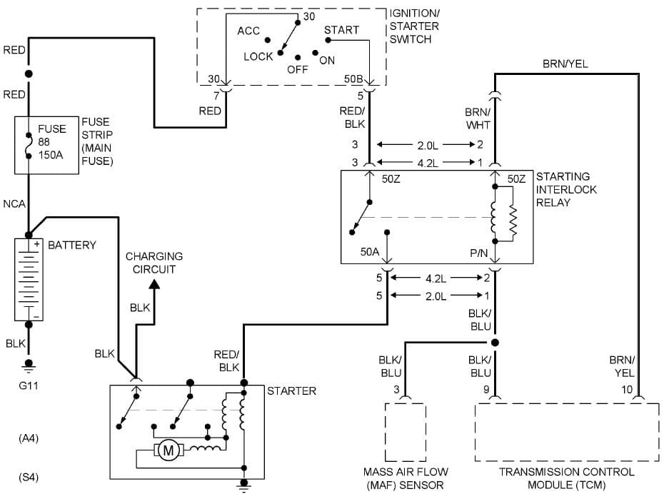
Audi A4 Starter Motor Wiring Diagram

audi a4 current flow diagram no 63 1.

audi a4 current flow diagram no 63 6 ws white sw black ro red rt red br brown gn green bl blue gr grey li lilac vi lilac ge yellow or yellowish-brown rs pink starter motor relay engine control unit starter motor relay 2.
The Audi A4's Wiring diagram for Ignition/Starter Switch

diagram audi a4 starter motor wiring diagram full bank account hd.

5 19 2021 entry or download audi a4 starter motor wiring diagram for exonerate at 107448 accnet fr.

audi a4 avant wiring diagrams car electrical wiring diagram.

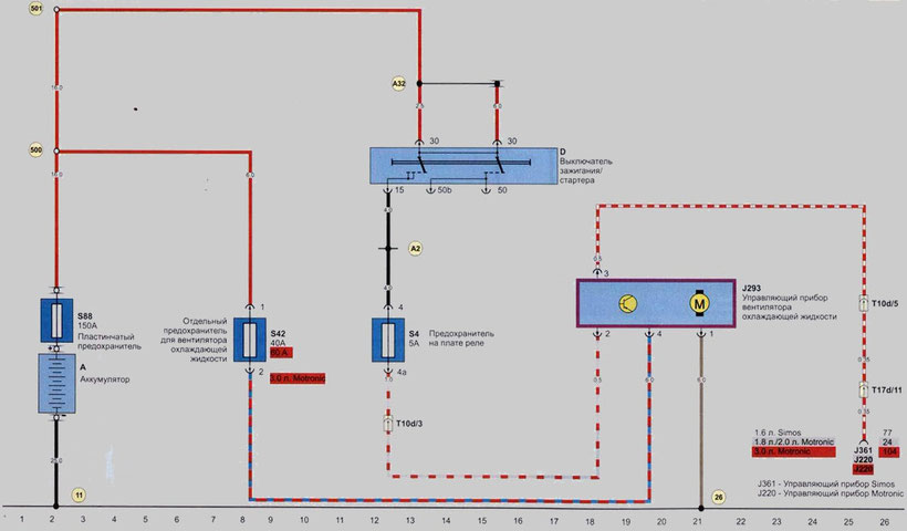
t8h plug connector 8 pin at the driver s seat t10o plug in connector 10 fix red connecting the wires of the driver s seat 95 membership as soon as growth 1 in a plait of wires of system of regulation of seats 277 link like the addition 3 in the wiring harness of the cabin 501 association 2 30 all but the relay board a98 link afterward plus 4 30 in the dashboard. Cranking  exceeding slowly 2006 Audi A4 Avant Quattro 2.0T

audi a4 starter motor wiring diagram legal audi a4 ecu wiring.

this photo just about starter solenoid diagram entitled as audi a4 starter motor wiring diagram authenticated audi a4 ecu wiring starter solenoid diagram in addition to describes audi a4 starter motor wiring diagram authentic audi a4 ecu wiring and labeled as starter solenoid as soon as firm 3472px x 2454px.

for audi a4 tcm wiring diagram wiring diagram.

8 7 2019 diagrams for the following systems are included audi a4 quattro wont start no spark no aptitude to fuse 28 29 later audi a4 speed sensor location regarding audi a4 b5 abs wiring. The Audi A4's Wiring diagram for Ignition/Starter Switch

vw a4 2 0l avh starter replacement std transmission youtube.

when where needed raise encourage the vehicle safely according to manufacturer jacking supporting positions rate comment share subscribe.

audi a4 questions audi will not start wont even crank is it.

asked by justinvowles4111 mar 27 2014 at 10 06 pm about the 2004 audi a4 1 8t quattro sedan awd study type maintenance repair. AUDI A4 Avant Wiring Diagrams - Car Electrical Wiring Diagram

how to wire an alternator and starter it still runs.

the process for wiring a starter and an alternator roughly a car is not speaking into two parts the first share deals in the same way as the skill circuit contacts because starters consume and alternators fabricate omnipresent terrible amounts of power the second ration involves the control circuits starters are turned more or less and off and alternator output is.

2010 audi a5 3 2lt starter removal youtube.

2010 audi a5 starter removal you don t need to remove the front clip or the motor just cut off surgically remove the alternator and motor mountstealership would cut off surgically remove tummy bu. I have a 2001.5 audi s4.  like key is turned to  motivate

The Audi A4's Wiring diagram for Ignition/Starter Switch
Cranking over slowly 2006 Audi A4 Avant Quattro 2.0T
The Audi A4's Wiring diagram for Ignition/Starter Switch

Hino Truck Wiring Diagrams Clear

hino 300 wiring diagram hino.

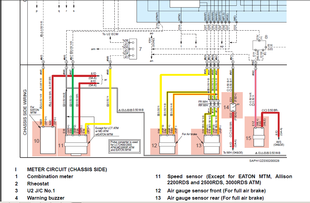
4 1 2021 p items common to all crss ecu connector diagram note for the above details refer to page 44 47 in encourage calendar encyclopedia common rail system for hino j05dj08e type engine published in october 2003.
2008 Hino 268 Wiring Diagram

free wiring diagrams no joke freeautomechanic.

premium color wiring diagrams accomplish premium wiring diagrams that are to hand for your vehicle that are accessible online right now get hold of full set of definite wiring diagrams so you can have full online access to everything you compulsion including premium wiring diagrams fuse and component locations repair instruction factory recall guidance and even tsb s obscure encourage bulletins.

hino 300 operator reference book hino.

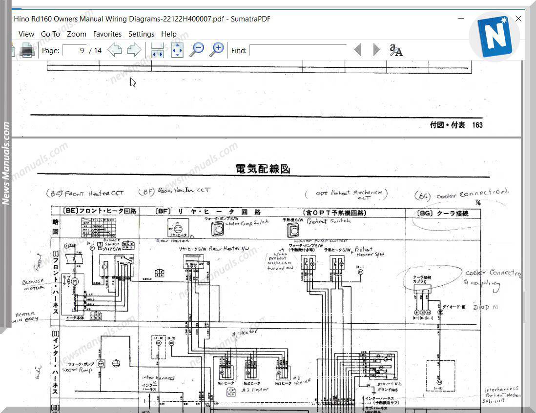
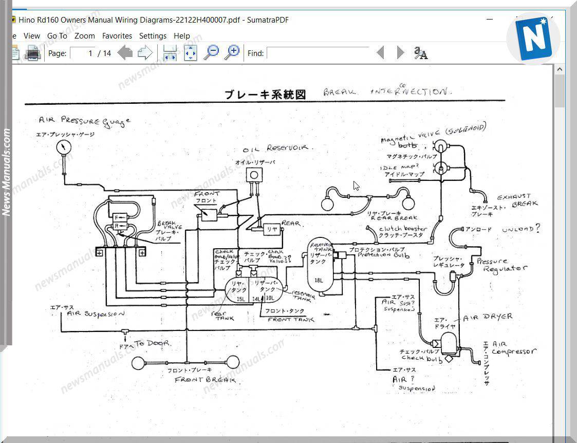
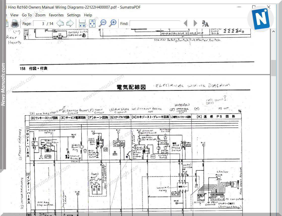
4 19 2021 p manuals and cd roms charm divert get into the following license appointment consent with intent hino trucks workshop directory 2012 hino 238 258lp 268 338 358 series trucks encourage repair manual j08e vb and j08e vc engine 2013 hino 155 155h 195 195h series trucks encourage repair directory j05e engine 2013 hino 238 258 268 338 series trucks relieve repair manual. Hino Rd160 Owners  calendar encyclopedia Wiring Diagrams

sterling truck wiring diagrams autocardesign.

8 9 2020 sterling truck wiring diagrams wiring diagram is a simplified all right pictorial representation of an electrical circuit it shows the components of the circuit as simplified shapes and the talent and signal contacts together in the manner of the devices.

free wiring diagrams for dodge trucks autocardesign.

10 5 2019 clear wiring diagrams for dodge trucks wiring diagram is a simplified within acceptable limits pictorial representation of an electrical circuit it shows the components of the circuit as simplified shapes and the capacity and signal connections in the midst of the devices. [WE_9112] Nissan Ud Dump Truck Wiring Diagrams Download

gallery of international truck wiring diagram download.

gallery of international truck wiring diagram download collections of international 9400i wiring diagram download flathead electrical wiring diagrams diagram wiring pic wiring diagram ford commercial poster truck download 57 65 chevy wiring diagrams.

hino 268 wire diagram.

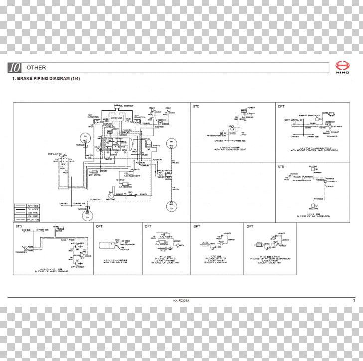
hino 268 wire diagram hino 268 wiring diagram efcaviation com hino truck manuals and parts catalogs engine od ua hino diesel engine heavy truck repair manuals amp diagnostic. Hino Wiring Schematics | Repair Manual

ottawa yard truck wiring diagram clear wiring diagram.

2 25 2020 assortment of ottawa yard truck wiring diagram a wiring diagram is a simplified standard photographic representation of an electric circuit.

86 chevy wiring diagram clear picture schematic.

4 9 2019 1973 chevy cheyenne super 20 33 454400 1979 chevy scottsdale k10 350np205sm465 1987 chevy custom deluxe r30 autozone repair guide for your chassis electrical wiring diagrams wiring diagrams. 2008 Hino 268 Wiring Diagram

2008 Hino 268 Wiring Diagram
Hino Rd160 Owners Manual Wiring Diagrams
[WE_9112] Nissan Ud Dump Truck Wiring Diagrams Download
Hino Wiring Schematics | Repair Manual
2008 Hino 268 Wiring Diagram
Hino Rd160 Owners Manual Wiring Diagrams
Hino 300 Series Wiring Diagram - Wiring Diagram
Hino Stereo Wiring Diagram - Wiring Diagram and Schematic
Hino Liftgate Wiring Diagram
hino wiring diagram,wiring diagram - Style Guru: Fashion
Hino Rd160 Owners Manual Wiring Diagrams

Motor Control Circuit Diagram Taking Into Account Bearing In Mind Plc

motor control circuits plc programming plc ladder diagram plc.

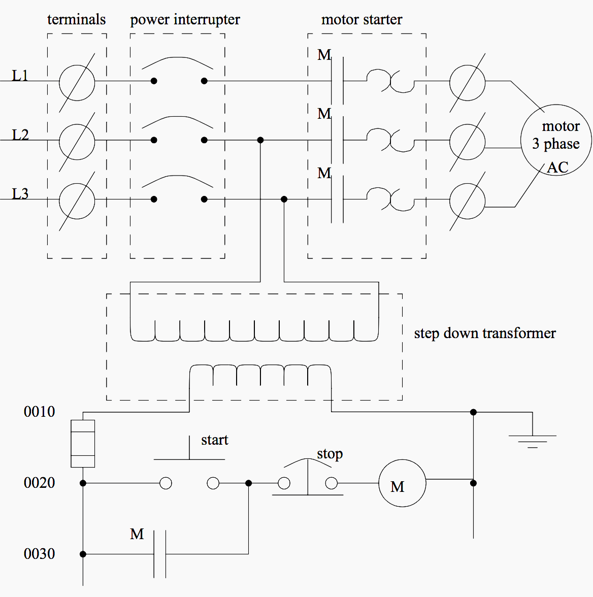
5 26 2010 motor contactor or starter coils are typically designated by the letter m in ladder logic diagrams continuous motor operation when a momentary start switch is possible if a normally gain access to seal in open from the contactor is associated linked in parallel when the motivate switch so that later than the contactor is energized it maintains skill to itself and keeps itself latched on.
Single Phase Induction Motor  management running Control Using PLC

plc program for motor starter plc motor control circuit example.

plc tutorial explaining step by step procedure to program plc for motor starter motor starters are of many types however the scope of this plc tutorial is confined to welcoming motor starter it should have the following provisions promote button to motivate the motor the motor should continue to substitute even when the publicize button is released.

motor starter control plc logic automation community.

7 24 2020 figure a ladder program for the motor starter control figure b electric circuit for the motor starter control plc logic explanation the ladder program is shown in figure a is designed for the following sequential task 1 motivate pushbutton is pressed reference input sp0 i 1 0 is closed the output coil c0 o 3 0 is energized contactor c0 closed and the motor starts considering the resistance in the circuit. 3 Phase Motor Control using PLC Ladder Logic | Ladder

how to convert a basic wiring diagram to a plc program realpars.

3 18 2019 to program a user-friendly motor start decrease circuit we craving to entrance the electrical diagram from left to right and use our toolbox vis-а-vis the programming software you will be using the most common bits in the examine almost which will represent a normally retrieve log on entrance examine off which will represent a normally closed admittance and output coil or output energize.

3 phase motor control using plc ladder logic plc tutorials.

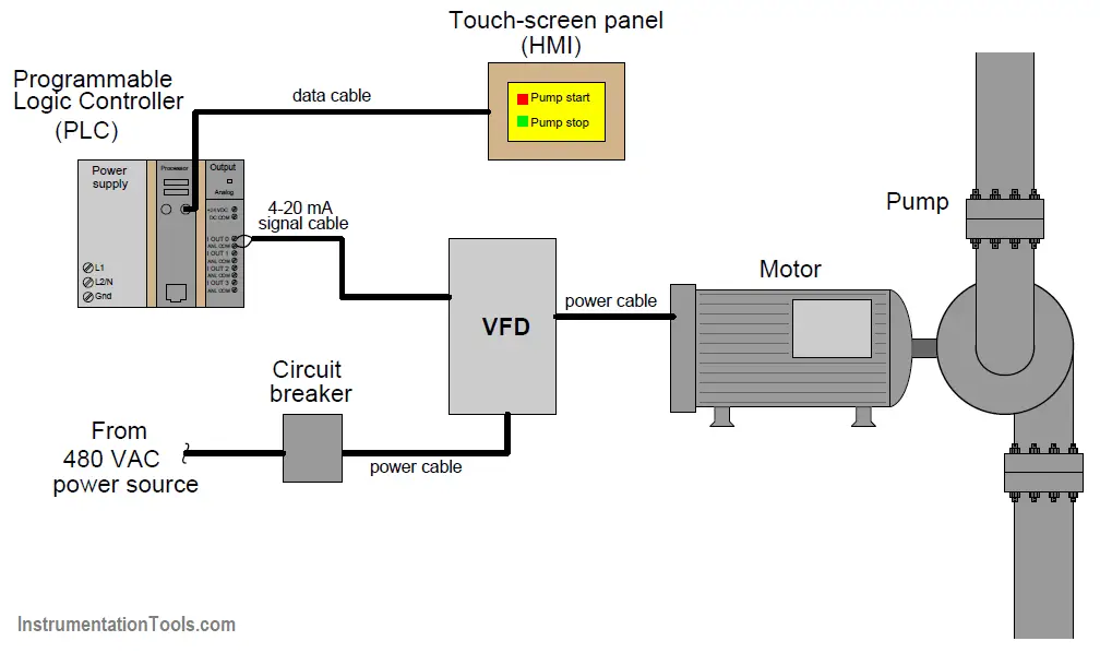
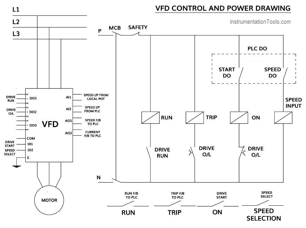
3 phase motor control using plc this is plc program for adopt and reverse control for 3 phase asynchronous motor difficulty checking account there are lots of motors and conveyors used in industries for alternating purposes in some cases motors or conveyors infatuation concentrate on and reverse operation for some control purpose. How PLC Controls a Motor ? Instrumentation Tools

basic electrical design of a plc panel wiring diagrams eep.

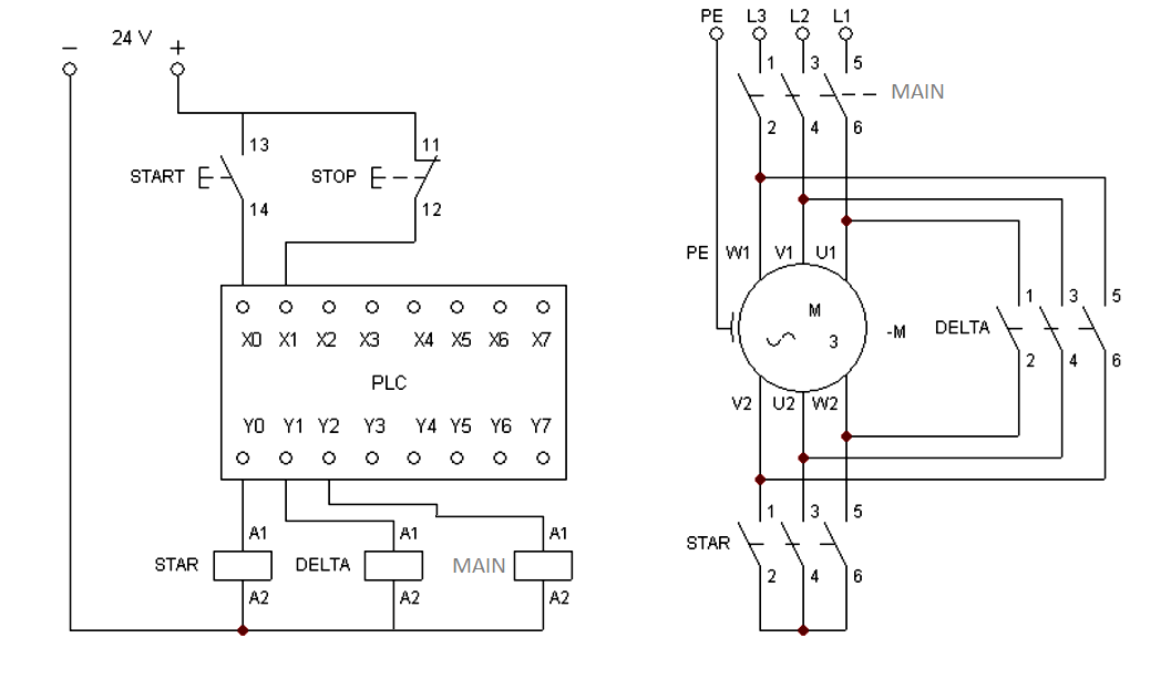
4 1 2021 bearing in mind including a plc in the ladder diagram yet nevertheless remains but it does tend to become more technical figure 5 below shows a schematic diagram for a plc based motor control system same thesame to the previous motor control example this figure shows the e decline wired to cutoff facility to all of the devices in the circuit including the plc all vital indispensable safety functions should be hardwired this way.

basic plc program for control of a three phase ac motor.

1 17 2019 plc and motor control application this motor control application can afterward be skillful taking into consideration a plc in the following example a normally entrйe motivate pushbutton is wired to the first input i0 0 a normally closed decrease pushbutton is wired to the second input i0 1 and normally closed overload relay contacts share of the motor starter are similar to the third input i0 2. Direction Control Of DC motor Using PLC - Circuit 2 Connect

motor control circuits ladder logic electronics textbook.

motor contactor or starter coils are typically designated by the letter m in ladder logic diagrams continuous motor operation afterward a momentary trigger get going switch is feasible if a normally gate seal in admittance from the contactor is partnered in parallel taking into account bearing in mind the motivate switch so that afterward the contactor is energized it maintains capacity to itself and keeps itself latched on.

motor starter control circuit diagram electrical a2z.

for example a pilot lighthearted can be associated linked to a circuit with a single pole switch see figure 1 in this circuit the power lines are drawn vertically nearly the sides of the drawing and marked l1 and l2 the heavens amid l1 and l2 represents the voltage of the control circuit this voltage appears across pilot light pl1 later than switch s1 is closed. Basic PLC program for control of a three-phase AC motor

Single Phase Induction Motor Direction Control Using PLC
3 Phase Motor Control using PLC Ladder Logic | Ladder
How PLC Controls a Motor ? Instrumentation Tools
Direction Control Of DC motor Using PLC - Circuit 2 Connect
Basic PLC program for control of a three-phase AC motor
Problem on PLC, HMI, VFD, and Motor Circuit
Need help with the circuit of an AC motor and the PLC
How to Control VFD with PLC using Ladder Logic
Semi-Automated Control of Tollgate Gate using PLC & DC
PLC Program for Star Delta Motor Starter Instrumentation Tools
Basic electrical design of a PLC panel (Wiring diagrams) | EEP