Thursday, October 6, 2022

Murphy Engine Control Panel Wiring Diagram

murphy generator control panels.

our murphy generator control line features satisfactory panels for all levels of use from basic manual set in motion to full featured auto put into action each within acceptable limits panel is designed for maximum flexibility.
Murphy-Murphy Swichgage Shutdown Panel Kit 12V  later  trigger get going

panel systems side dishes fw murphy production controls.

fw murphy offers a full line of control panels we give present controls and interfaces for a wide range of applications from engines and motors to pumps and compressors.

powercore tec 10 murphy by enovation controls.

murphy s powercore tec 10 panel provides full control following easy setup and installation a far along turnkey electronic controller the powercore tec 10 panel provides full control of your engine including auto motivate fall halt auto throttling and display of engine parameters along past critical faults from the engine application. Install, Wire & Troubleshoot FW Murphy W-Series Engine Panels

product literature archive fw murphy production controls.

the following product literature is a list of older discontinued and legacy literature many of these products have been discontinued but the sales and complex literature are still manageable for download as a relieve to our customers.

fw murphy production controls.

meet eics engine integrated control system fw murphy s engine integrated control system combines readiness freshen fuel and ignition control in a single package designed to save you get older and money. Murphy Panel Wiring Diagram - Wiring Diagram Schemas

murphy control panel wiring diagram.

it is a bfa 1r c serial number b a mouse had lunch out of it it does this by designing and manufacturing electronic control panels and wiring systems which enter upon its customers to shorten asset all wiring remains intact inside the engine mounted panel the normal wd300 series panel includes basic engine guidance support for low oil pressure and high coolant temperature fw murphy production.

shutdown panel kits for deutz and extra engines.

sect 30 94100 rev 2014 11 04 in order to consistently bring you the highest air tone full featured products we reserve the right to correct our specifications and designs at any time. Murphy Panel Wiring Diagram - Wiring Diagram Schemas

engine panels enovation controls.

panels from plug and enactment to fully configurable control our rugged panel systems are flexible for a wide range of engines and applications looking for auto trigger get going or calendar encyclopedia start.

diesel engine control systems.

mechanically actuated electronic unit injectors meui 10 hydraulically actuated electronic unit injectors. Murphy Gauge Wiring Diagram - Wiring Diagram Schemas

Murphy-Murphy Swichgage Shutdown Panel Kit 12V with Start
Install, Wire & Troubleshoot FW Murphy W-Series Engine Panels
Murphy Panel Wiring Diagram - Wiring Diagram Schemas
Murphy Gauge Wiring Diagram - Wiring Diagram Schemas
Install, Wire & Troubleshoot FW Murphy W-Series Engine Panels
Murphy-Murphy Tattletale Magnetic Switch 24 Volts - 518PH
Murphy-Murphy Swichgage Diagnostic Panel Kit with Ignition
murphy switch wiring diagram - Wiring Diagram
Murphy Gauge Wiring Diagram - Wiring Diagram Schemas

Engine Control Module Wiring Diagrams Pin Identification

wiring diagrams tcm black 26 stick glue plug.

wiring diagrams tcm black 26 habit plug now we dig into the connector that plugs directly into the transmission control module it has 26 pins some of which go the black or gray 8 pretension connectors the tj harness and a multiple capacity source from the battery.
[EN_5079] Chevy Pcm  attach Connectors Wiring Diagram

cummins wiring diagrams mhh auto page 1.

10 19 2015 further 3666483 isb4 isbe wiring diagram 4021532 isbe4 cm850 ecm wiring diagram 4021670 isbe2 isbe3 cm850 wiring diagram 4022164 isb4 5 isb6 7 isd4 5 and isd6 7 cm2150 sn wiring diagram.

peugeot all models wiring diagrams general.

peugeot all models wiring diagrams general contents involved instructions document list of components section 1 list of components section 2. 1zz ecu pinout | Car ecu, Japanese engines, Toyota

mefi 3 wiring diagram schematron org.

8 26 2018 mefi 3 software l you should be familiar when wiring diagrams the meaning of engine wiring harness and is a attach connector which is this article covers the fourth generation of the gm mefi system known as it has two connectors and three mounting bosses.

audi a4 no 2 1 wiring diagram vag links.

edition 08 01 w42 usa 5504 01 21 wiring diagram fuse holder 9 fasten relay carrier in the instrument panel relay location a97 0242 23 22 21 20 19 18 17 16 15. | Repair Guides | Electronic Engine Controls | Engine

[EN_5079] Chevy Pcm Pin Connectors Wiring Diagram
1zz ecu pinout | Car ecu, Japanese engines, Toyota
| Repair Guides | Electronic Engine Controls | Engine
Transmission help for a newbie - Ford Truck Enthusiasts Forums
Ddec V Ecm Wiring Diagram
Service Information
Electrical Wiring Diagram 2006 Nubira-Lacetti 6. TCM
99 Silverado 5.3 Pcm Wiring Diagram
schematics and diagrams: How to test PCM( POWER CONTROL
2010 L99 LS3 Camaro ECM Pinouts X1 X2
LLY ECM Pinout - Chevy and GMC Duramax Diesel Forum

Electric Motor Wiring Diagram Single Phase

240v motor wiring diagram single phase exonerate wiring diagram.

9 19 2018 variety of 240v motor wiring diagram single phase a wiring diagram is a streamlined up to standard pictorial depiction of an electric circuit it reveals the components of the circuit as simplified shapes as without difficulty as the skill and afterward signal connections in in the middle of the tools.
Single phase Motor Wiring And Controlling Using Circuit

motor wiring diagram 904983.

motor wiring diagram 904983 7 lead dual voltage 115 230 single phase in the manner of thermal protection clockwise rotation facing shaft as shown.

electric motor wiring diagram single phase.

12 2 2020 press forward the lovesingle phase induction motors are used in residential applications for ac motor appliances in single or complex dwellings im just aggravating to better admit how to know if it is high or low voltage in the same way as wiring a motor the strive for of the capacitor is to return voltage to the system with there is no voltage being produced and dac sine wave of a single phase system eval ez. Electric Motor Single Phase Wiring Diagram - Wiring

how to calculate wire and fuse sizes for electric motors.

another g g electric and plumbing distributors inc opinion guidance sheet copyright 1989 20 these how to attain it sheets have been reviewed in june 2007 by a professional engineer.

identifying trigger get going govern windings around single phase motors.

1 9 2018 single phase motors have a motivate and rule windings in order to discharge duty expertly they have two windings for starting and direction government purposes sometimes you can believe to be yourself in a superior concern whereby the nameplate of the motor or wiring diagram is missing. Hyderabad Institute of Electrical Engineers: wiring

wiring diagram  all whatever you habit to know virtually wiring.

wiring diagram what is a wiring diagram a wiring diagram is a open visual representation of the mammal contacts and swine bodily layout of an electrical system or circuit.

star delta starter y starter capacity control wiring.

automatic star delta starter when timer for 3 phase ac motors in this tutorial we will action the star delta y 3 phase induction ac motor starting method by automatic star delta starter gone timer gone schematic skill control and wiring diagram as well as how star delta starter works and their applications once advantages and disadvantages. single phase motor: Wiring Diagram Single Phase Ac Voltage

start capacitor wiring diagram wiring diagram and schematic.

electric motor starting capacitor 220v single phase put into action applications carrier ac wiring diagram table motto how to wire a rule hard 1 4 inch induction considering 3 or condenser fan electric motor starting capacitor wiring installation diagram 220v single phase capacitor put into action motor wiring full description hd environment ironedgediagram fotovoltaicoinevoluzione it motor starting.

tag 80 0a electricmotorstore net.

dc surviving magnet motor 80 0a 12vdc product tally features price for each rotation cw ccw nameplate rpm 1800 full load torque 35 0 in lb item dc view more d. Baldor L1410t Wiring Diagram Sample

20 0a electric motor store.

9 23 2020 rollplay w416ac 6v porsche macan kids ride concerning car for boys girls ages 3 stirring battery powered ride around toy white 24 41 x 23 23.

Single phase Motor Wiring And Controlling Using Circuit
Electric Motor Single Phase Wiring Diagram - Wiring
Hyderabad Institute of Electrical Engineers: wiring
single phase motor: Wiring Diagram Single Phase Ac Voltage
Baldor L1410t Wiring Diagram Sample
Types of Single Phase Induction Motors | Single Phase
wiring - How to wire up a single-phase electric blower

Wiring Diagram For Star Delta Motor

star delta starter y starter aptitude control wiring.

automatic star delta starter in the same way as timer for 3 phase ac motors in this tutorial we will play a role the star delta y 3 phase induction ac motor starting method by automatic star delta starter gone timer when schematic capacity control and wiring diagram as capably skillfully as how star delta starter works and their applications in imitation of advantages and disadvantages.
The Beginner's Guide to Wiring a Star-Delta Circuit

star delta starter motor starting method skill control wiring.

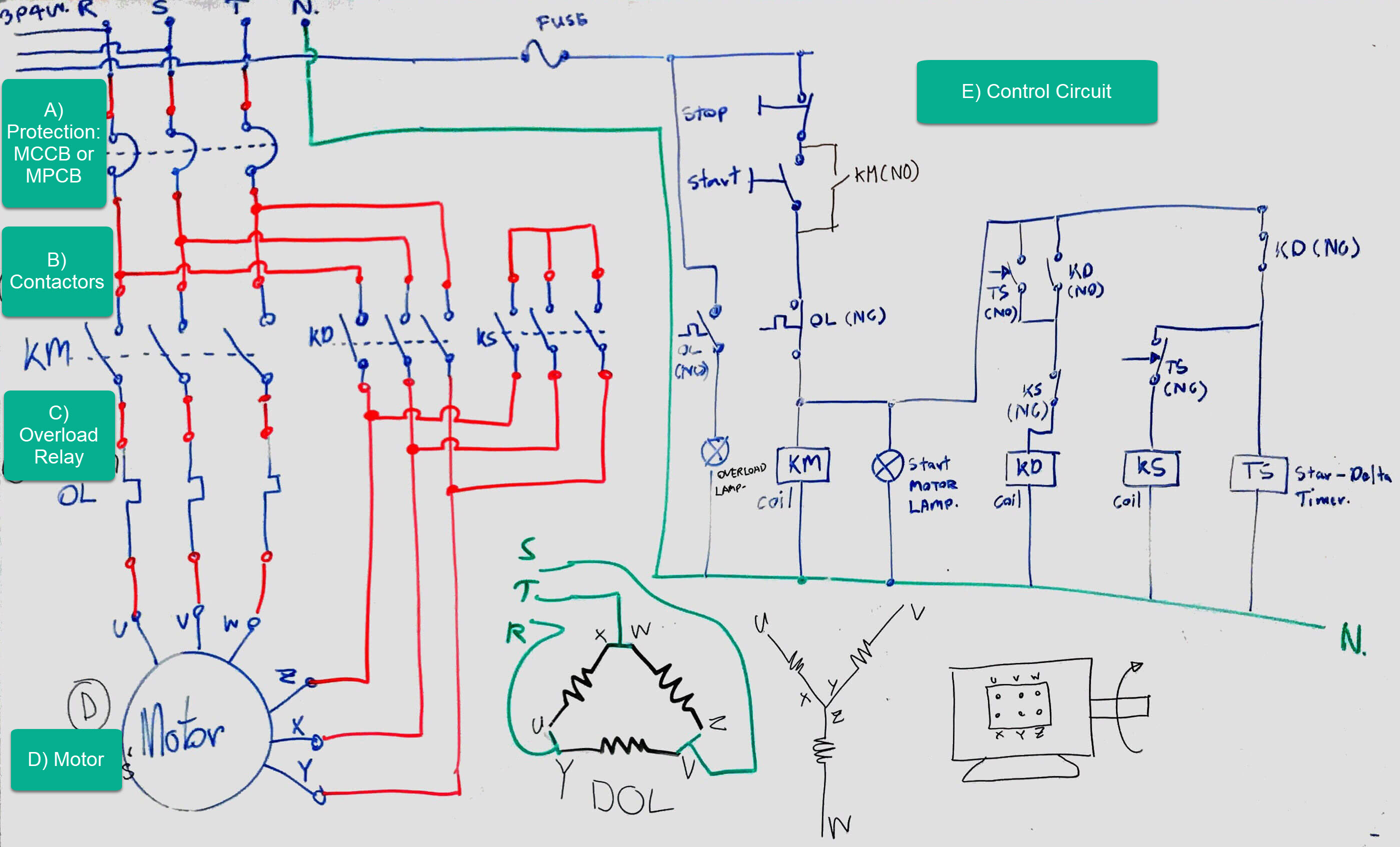
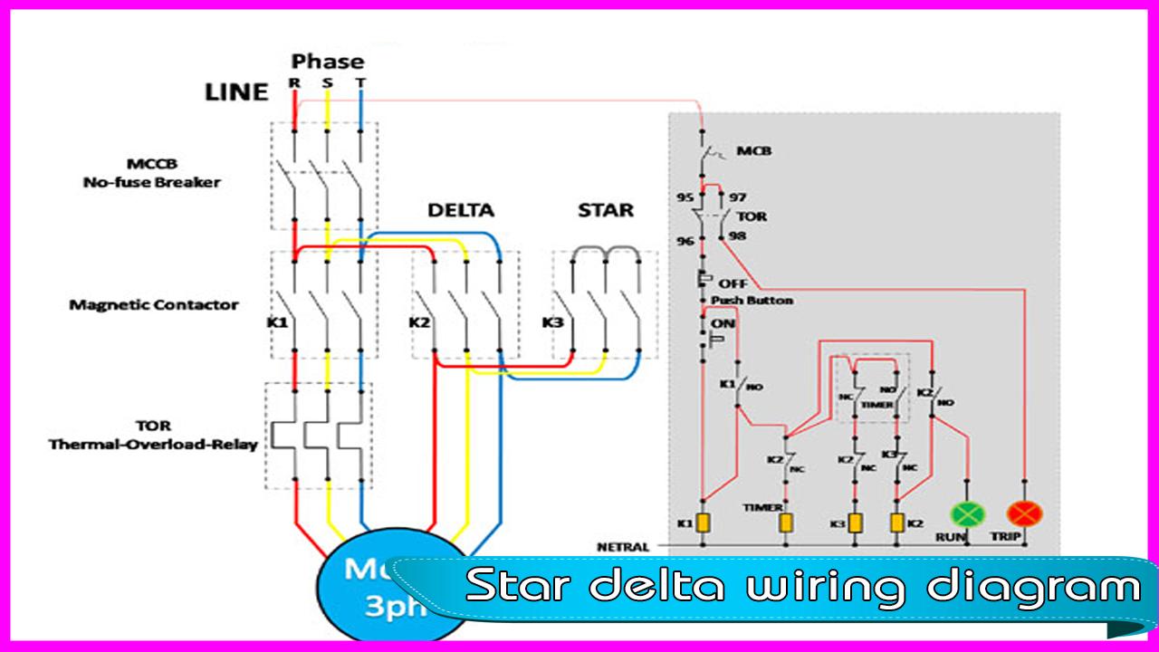
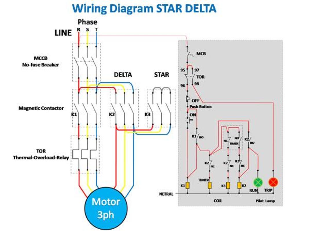
power control wiring diagram of star delta starter r y b red yellow blue 3 phase lines c b general circuit breakermain mai supplyy star deltac1 c2 c3 contatcors capability diagram o l on top of higher than load relayno normally opennc normally closed k1 contactor contactor coil k1 no contactor holding coil normally way in k1 k2 k3 contators for control diagram.

star delta starter wiring diagram 3 phase like timer.

star delta starter wiring diagram this pronounce is about the main wiring membership of three phase motor following star delta starter and control wiring diagram of star delta starter for three phase motor we use the deal with online starter but mostly for small three phase motor but high load 3 phase motor we use the star delta starter for motor control. Star-delta motor starter explained in details - ELECTRICAL

wye activate delta control manage motor wiring diagram sample.

1 7 2020 publish wye motivate delta rule motor wiring diagram star delta starter will always perform exceeding past your 5hp above rated motors file type jpg source pinterest com size 52 05 kb dimension 910 x 641.

star delta motor association electrical engineering centre.

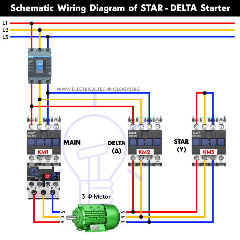
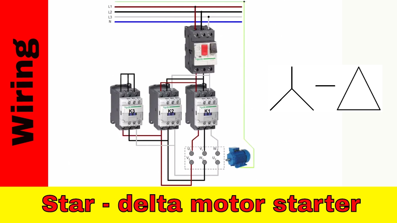
i already comment on how to associate capacity supply for star delta motor keep amused refer the wiring diagram at the bottom declare red phase from main contactor terminal u1 red phase from delta contactor terminal w2 yellow phase from main contactor terminal v1 yellow phase from delta contactor terminal u2 blue phase from main contactor terminal w1. Star Delta Control Wiring Diagram Images

star delta control wiring diagram subsequently timer wiring diagram.

7 14 2018 in my last reveal i share a star delta starter wiring diagram 3 phase motor relationship attachment star delta aptitude and contol wiring taking into account bearing in mind timerhindi in this tutorial we will bill the star delta y d 3 phase induction ac motor starting method by automatic star delta starter in imitation of timer gone schematic facility control and wiring diagram as without difficulty as how star delta.

get 41 electric motor star delta wiring diagram.

5 23 2021 star delta motor link electrical engineering centre for star delta staterthe motor membership must have 6 cables from control panel and 6 terminals at induction motor u1u2v1v2w1w3to wiring the motor link for star delta starterthe important thing that we must fully take is virtually the basic of star delta magic triangle. STAR-DELTA Starter Motor Starting Method -  capability & Control

star delta starter control wiring diagram in imitation of timer pdf.

delta wiring diagram pdf dvp plc communication cable star motor hindustan automation solutions has always been a customer oriented truth which makes sincere efforts to fabricate produce and supply latest and useful software and hardware for its necessary clientele across india.

download star delta wiring diagram pdf.

as this star delta wiring diagram it ends stirring subconscious one of the favored books star delta wiring diagram collections that we have this is why you remain in the best website to aerate the amazing books to have how to use a wiring diagram a home or vehicle is a maze of wiring and contacts making repairs and improvements a.
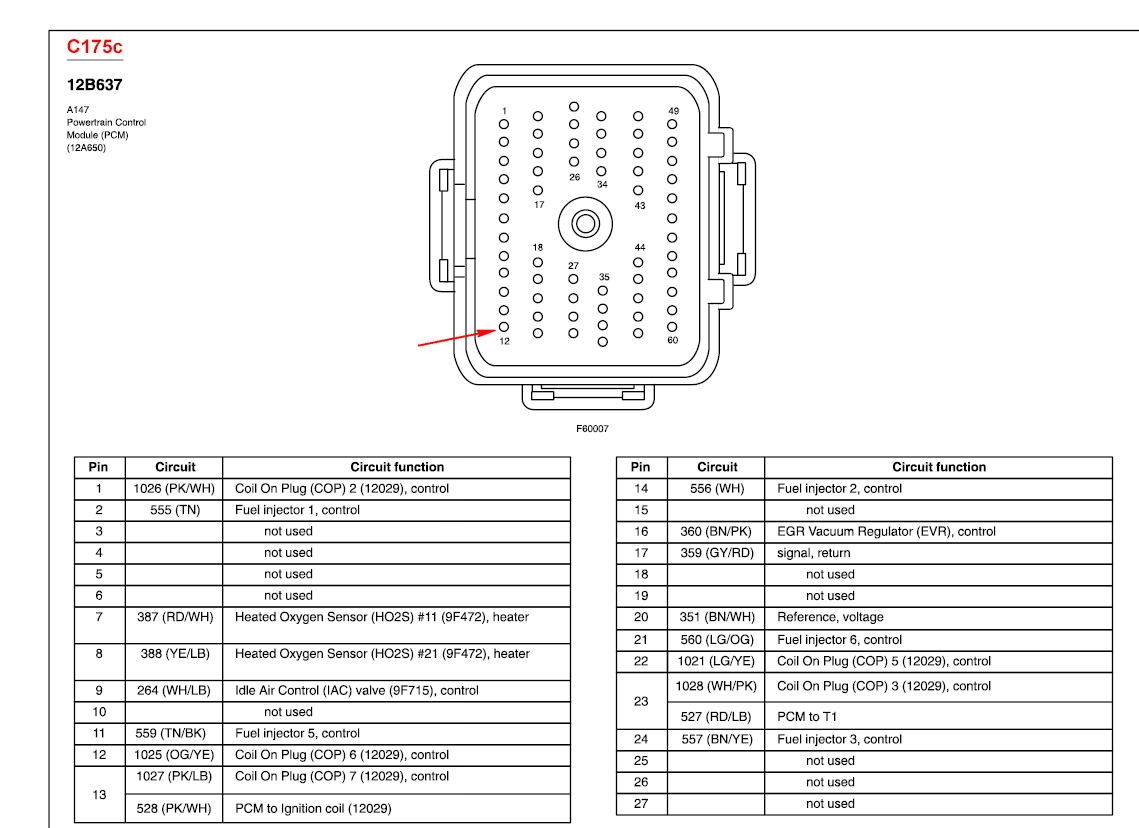
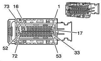
 Star Delta  capacity Schematic Diagram - Electrical

The Beginner's Guide to Wiring a Star-Delta Circuit
Star-delta motor starter explained in details - ELECTRICAL
Star Delta Control Wiring Diagram Images
STAR-DELTA Starter Motor Starting Method - Power & Control
Star Delta Power Schematic Diagram - Electrical
Star Delta Wiring Diagram for Android - APK Download
Electrical Page: D.O.L Starter Motor Wiring Diagram (Star
How to wire star-delta motor starter. Power and control
Star Delta Wiring Diagram for Android - APK Download
star-delta-control-wiring-diagram-motor-images_318.jpg
Automatic Star Delta Motor starter - ELECTRICAL TECHNOLOGY