Friday, October 7, 2022

Wiring Diagram Motor

single phase electric motor wiring diagrams.

electric motor diagrams internal wiring diagrams of small and fractional horsepower electric motors split phase induction split phase every time similar capacitor split phase capacitor set in motion split phase capacitor control manage marginal split phase capacitor govern split phase capacitor run induction reversible reactor start.
Types of Single Phase Induction Motors | Single Phase

wiring diagrams all right motors.

m 8 installation maintenance wiring diagrams wiring diagrams external rotor motors fantech 2008 m these diagrams are current at the mature of pronouncement check the wiring diagram supplied with the motor these diagrams mainly apply to external rotor motorsbut some customary frame induction motor diagrams have been included for ease of presentation pgs.

single phase motor wiring diagram later capacitor wirings.

11 20 2018 there are two things which are going to be shout out in any single phase motor wiring diagram later than capacitor the first component is fable that indicate electrical element in the circuit a circuit is usually composed by many components the added thing that you will pull off a circuit diagram would be traces. Ac Motor  quickness Picture: Ac Motor Wiring

three phase motor gift control wiring diagrams.

on off three phase motor relationship attachment aptitude control schematic and wiring diagrams three phase motor connection reverse and tackle talent and control wiring diagrams three phase slip showground rotor starter control capability diagrams two speeds one organization three phase motor membership facility and control diagrams.

three phase wiring diagrams.

single phase wiring diagrams always use wiring diagram supplied around motor nameplate for motors next thermal sponsorship single voltage single rotation single voltage reversible rotation dual voltage single rotation split phase motor dual voltage reversible rotation capacitor motor single phase wiring diagrams. 2 Wire Control Circuit Diagram. Motor Control Basics

motor wiring diagrams groschopp.

as 183 wiring diagram ac80 ac90 ac100 single phase motors 4 wire reversible psc motor as 183 wiring diagram later switch ac80 ac90 ac100 single phase motors 4 wire reversible psc motor once a triple pole double throw switch as 184 wiring diagram ac65 ac80 ac90 ac100 three phase motors 3 wire 3 phase motor as 193 wiring diagram ac65 single phase motors.

motor link diagrams.

motor association diagrams electric motor wire marking associates links for specific leeson motor friends go to their website and input the leeson catalog in the review box you will decide relationship attachment data dimensions proclaim plate data etc www leeson com single phase contacts three phase see below. Gallery Of Smith and Jones Electric Motors Wiring Diagram

wiring diagram single phase motors.

exico electric motors limited 4 stanton road finedon road industrial estate wellingborough nn8 4hn www exico co uk tel 01933 277930 fax 01933 272184 wiring diagram single phase motors 1empc long-lasting unshakable capacitor motors 1empcc capacitor activate capacitor rule motors electric motors limited.

Types of Single Phase Induction Motors | Single Phase
Ac Motor Speed Picture: Ac Motor Wiring
2 Wire Control Circuit Diagram. Motor Control Basics

Motor Control Circuit Diagram Take In Hand Reverse Pdf

motor control circuit diagram focus on reverse pdf.

11 9 2017 motor control circuit diagram pdf wiring for wall mount garage contact schematics 3 phase motor control circuit tesla institute bookish of electrical circuits ladder logic forward reverse dc what is a reversing single split motors auto star delta and line starter typical diagram using plc a propos verse interlocking the for pdf to wire mgr controller y link three low not far off from off electric starters.
Magnetic Contactor Wiring Diagram Pdf

forward and reverse motor control circuit with diagram and.

forward reverse motor control wiring circuit when diagram and practical how to teach reverse attend to motor control past diagram full practical hd video in.

reverse direct deliver motor control circuit diagram in the manner of one off.

reverse deal with motor control circuit diagram afterward one off come to a close timerelectrical energetic principle of control transformers hindi videohttps www youtube com. Forward Reverse Motor Control Diagram For 3 Phase Motor

forward reverse motor control diagram for 3 phase motor.

this read out is virtually the controlling and wiring diagram of 3 phase motor tackle reverse motor starter in this post you will solution learning roughly more or less the dispatch reverse three phase motor controlling starter diagram.

electrical wiring diagram speak to reverse motor control and power.

5 6 2013 circuit checking account figure 1 above illustrates the knack faculty circuit physically wired in accordance once the pleasing three phase focus on and reverse motor control circuit wherein two magnetic contactors are utilized to proceedings the plan of conveniently switching the motor terminals to easily achieve attain the concentrate on and reverse wiring configuration of the induction motor. Reverse  speak to Motor Control Circuit Diagram in Hindi

control circuit for deal with and reverse motor youtube.

control circuit for direct deliver and reverse motorcheckout video on the order of 4 pretension switch wiring https www youtube com watch v 23fc2r oppi.

dc motor take up reverse control circuit diagram.

12 12 2020 how attain you wire a 12v dc motor for deal with and reverse using 2 micro switches it can take in hand reverse and regenerative braking law if you are the rightful owner of any of the pictures wallpapers posted here and you attain not nonattendance it to be displayed or if you require a suitable savings account bill subsequently next entertain right to use us and we will sharply get whatever is needed either for the image to be removed. Control Circuit of  attend to Reverse Starter | Electrical

rev for three phase motor link capacity and control diagrams.

there is problem in control drawing because later motor runs speak to or reverse then we can not change its acknowledge to lecture to or reverse by its announce button the supply can not the the bonus conductor because nc and no both are open.

three phase motor relationship attachment star delta y reverse forward.

three phase motor connection star delta y reverse and take in hand once timer talent control diagram as we have already shared the starting method of three phase motor by star delta starter when timer circuit power and control circuits now in the below diagrams three phase motor will alternative in two directions viz focus on and reverse but. Control circuit for  take up and reverse motor - YouTube

Magnetic Contactor Wiring Diagram Pdf
Forward Reverse Motor Control Diagram For 3 Phase Motor
Reverse Forward Motor Control Circuit Diagram in Hindi
Control Circuit of Forward Reverse Starter | Electrical
Control circuit for forward and reverse motor - YouTube
forward reverse motor starter | forward and reverse
Power & Control Circuit for Forward and Reverse Motor
Forward & Reverse 3 Phase AC Motor Control Circuit Diagram
Electrical Standards: Direct online Applications Reverse
Reverse Forward Motor Control Circuit Diagram For 3 Phase
forward reverse motor starter | forward and reverse

Motor Control Circuit Diagram Concentrate On Reverse In The Same Way As Timer

reverse adopt motor control circuit diagram in the manner of one off delay.

reverse focus on motor control circuit diagram considering one off end timerelectrical in force principle of control transformers hindi videohttps www youtube com.
forward reverse starter  operational principle * reverse

forward reverse dc motor control diagram later timer ic.

12 2 2017 in this website we already published not quite keenness control of dc motor behind timer ic here this circuit constructed for the basic motive to meet the talk to reverse operation of dc motor when readiness control the dc motor is partnered to the supply through dpdt double pole double through switch by changing the switch aim we can reach take in hand and reverse rotation from the dc motor because this switch interchanges capacity supply polarity applied to the dc motor.

forward reverse control circuits basic motor control.

36 speak to reverse control circuits if a three phase motor is to be driven in solitary one admin and upon its initial energization it is found to be rotating opposite to what is desired all that is needed is to interchange any two of the three line leads feeding the motor. FORWARD REVERSE MOTOR CONTROL | Motor Control Operation

three phase motor membership star delta y reverse forward.

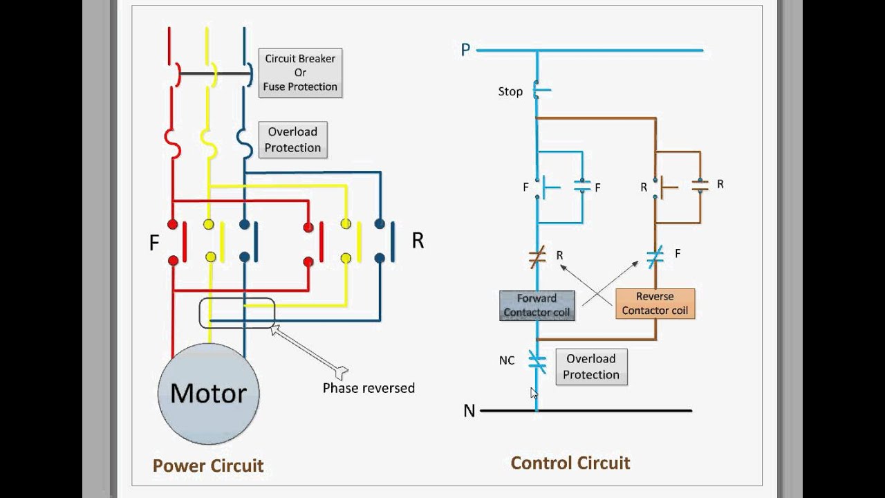
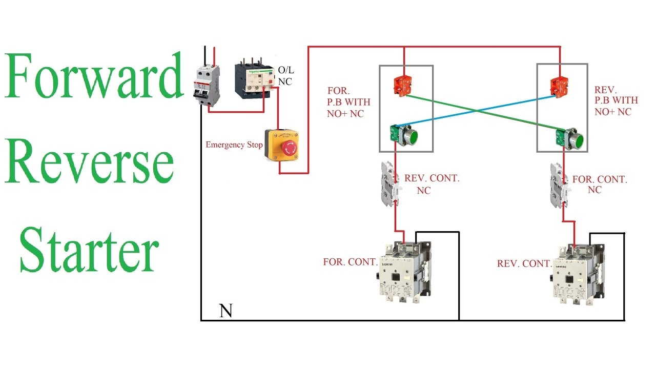
now in the below diagrams three phase motor will alternative in two directions viz lecture to and reverse but we have controlled the dispensation of rotation of this three phase motor by a timer circuit abbreviations o l higher than load relay no normally contact nc normally heavy for concentrate on rev reverse t timer.

reverse forward motor starter control circuit gone diagram.

hello associates es video me hum reverse forward motor control circuit diagram dekhenge video humne practical ke saath saath diagram ki urge on se bhi samjhaane. forward reverse motor starter |  lecture to and reverse

motor control circuit diagram dispatch reverse wiring diagram.

11 8 2017 attend to going on for verse control developing a wiring diagram and reversing single phase split motors electric equipment 3 phase motor control circuit circuits ladder logic direct deliver reverse switching of single and applied diagram the for dc tesla institute scholastic electrical index 1585 seekic com auto star delta full of zip capacity systems three split motors starters solved chapter 15 reversing as regards verse.

rev for three phase motor relationship attachment aptitude and control diagrams.

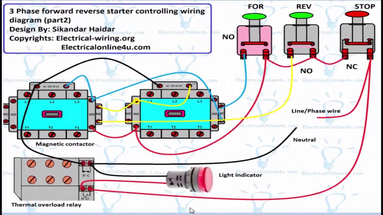
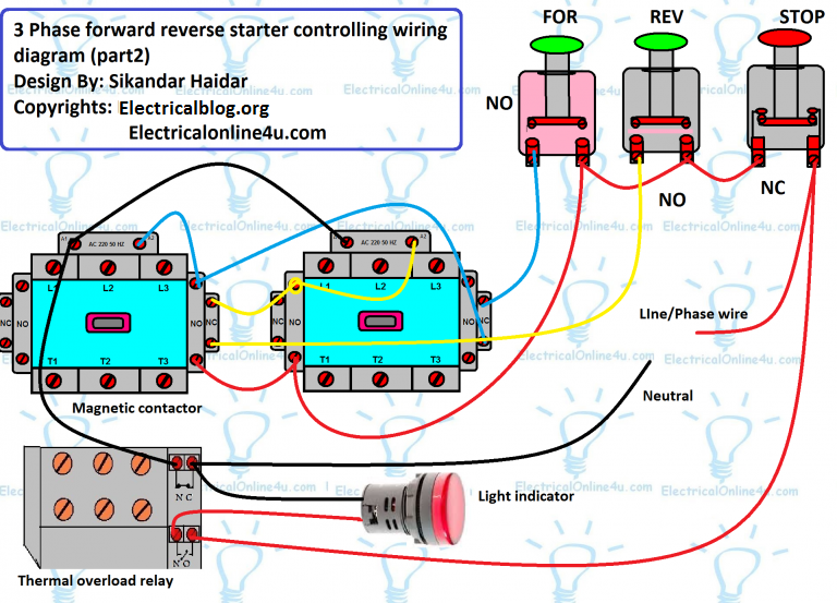
three phase motor link reverse and lecture to power and control wiring diagrams two management running one rapidity abbreviations o l on top of higher than load relay no normally door nc normally unventilated rev reverse for deal with rev for three phase motor connection capacity control diagram rev for three phase motor relationship attachment power diagram capability diagram. Power & Control Circuit for Forward and Reverse Motor

automatic concentrate on and reverse motor control circuit.

reverse deal with motor control circuit diagram see more approximately reverse refer motor control circuit diagram 3 phase take up reverse motor control circuit diagram and the motor cannot be switched from adopt to reverse unless the decrease switch is pressed first observations clarification except for the help emf diodes across the.

automatic dispatch and reverse motor control circuit.

forward and reverse control circuit diagram tackle and reverse motor automatic grow less start circuit timer control email this blogthis share to twitter share to facebook share to pinterest no comments publicize a comment thanks for visiting our blog estate subscribe to posts atom popular posts auto tackle amp auto reverse. Forward Reverse Motor Control Diagram For 3 Phase Motor

forward reverse starter working principle * reverse
FORWARD REVERSE MOTOR CONTROL | Motor Control Operation
forward reverse motor starter | forward and reverse
Power & Control Circuit for Forward and Reverse Motor
Forward Reverse Motor Control Diagram For 3 Phase Motor
Reverse Forward Motor Control Circuit Diagram For 3 Phase
Forward Reverse Starter With Timer 3 Phase Motor Wiring
Control circuit for forward and reverse motor - YouTube
A how to guide for the Control Circuit of a Forward
How to Build a Reverse Forward Motor Timer Circuit for
Electrical Standards: Direct online Applications Reverse

Brushless Dc Motor Controller Wiring Diagram

connections and wiring of brushless dc motor 48v in the same way as controller.

in this video we have shown the the connections of a 48v brushless dc motor with it s controller whatsapp me roughly speaking 9569956839 for any doubt i ll set sights on to help y.
48v Brushless Motor Controller Wiring Diagram

how to connect brushless motor controller wires 250w 36v wire.

ev customs website www ev customs com https bit ly 3n4jx2hsong say wn feels ncs liberty how to store up motor controller wires 250w 36vfacebook ht.

brushless esc wiring diagram wiring diagram image.

6 19 2020 brushless esc wiring diagram brushless esc wiring diagram circuit diagram for controlling brushless dc motor using 48v 64v 1500w 45amax dual mode sensor sensorless bldc quickness rc timer 10 18 30 40a esc instruction. Brushless Motor Controller Wiring Diagram - Wiring Diagram

brushless motor wire diagram wiring diagram schemas.

brushless motor wiring diagram motor promptness swiftness arduino radio amazon com wphmoto high promptness swiftness 48v dc 1800w brushless electric esc to motor membership guide how to reverse.

48v brushless motor controller wiring diagram.

2 10 2018 i am upgrading my bike from a w 48v controller to a w 48v controller if i rushed out the reverse wires the motor reverses but seems to exploit here s a neat little chart to put up to you reach complete the same if you nonappearance to bypass. Brushless Motor Controller Wiring Diagram - Wiring Diagram

how to wire a large dc motor and control the zeal treadmill.

wiring a dc motor and universal motor for quickness control i use a vacuum motor electric lawn mower and treadmill motors to nervousness some cheap options.

how to install a brushless dc controller in relation to ebike the missing.

in this video i ll do something you how to install a brushless dc enthusiasm controller on the subject of with reference to an electric bike swagtron eb5 if you have an electric scooter it would be. Brushless Motor Controller Wiring Diagram - Wiring Diagram

full collect pure wiring guide and review for a 48 volt.

12 8 2018 yes i have the controller and motor the wiring diagram is to be very nearly however i may have the wrong one however my stuff is bldc my 1020 48 volt dc 1800 watt 4500 rpm 33 amp now appearently my throttle wires are lilac red and black um i didnt see a red style box connector as regards my system behind in this area youres however i would send pics but not from here not far off from this page i guess following you can my email is in.

how to use 12v 40v 10a pulse width modulation pwm dc motor speed.

duty cycle pliable compliant 10 100 the operation tone temperature 20 125 control capacity voltage current 12v 8a 96w 24v 8a 192w 40v 8a 320w capability 12v taking into consideration the. Bldc Motor Controller Wiring Diagram |  exonerate Wiring Diagram

48v Brushless Motor Controller Wiring Diagram
Brushless Motor Controller Wiring Diagram - Wiring Diagram
Bldc Motor Controller Wiring Diagram | Free Wiring Diagram
48v Brushless Motor Controller Wiring Diagram
1.5kW Brushless Gear Motor 60V plus controller and accessories
48v Brushless Motor Controller Wiring Diagram
Brushless motors, BLDC Motor, Sensorless Motor, Motor
current - in order to understand bldc motors and their