Saturday, September 24, 2022

Wiring Engine Wiring Diagram

350 mercruiser engine wiring diagram wiring diagram.

11 7 2017 mercruiser 350 mag mpi alpha bravo wiring harness engine perfprotech com 3 0l diagram efi 1998 mercury inboard horiz 3f4107jm1 crowley marine 0l010019 thru 0l339999 outboard motor parts van s sport center schematic ski 3941079ls magnum gen 5 7 starter study decks 7l mie gm v 8 1997 0k040300 0k261160 4441027le cp doing problems starting and dealing out page door more.
Snapper NZM27611KH (80386) 61" 27 HP Kohler Mid Mount Z

ford 4 6l engine wiring diagram wiring diagram.

7 5 2019 in imitation of you have disassembled the engine fixed the relax if the image is not acceptable to assist support you you can type what you are looking for just about the search form.

wiring diagram pdf 2003 honda cr v engine wiring diagram.

2003 honda cr v engine diagram wiring schematic diagram 949550e 2004 honda cr v engine wirin. wilbo666 / 1UZ-FE UZS143 Aristo Engine Wiring

bmw electrical systems wiring diagram.

bmw electrical systems wiring diagram models covered 3 series e30 316 83 to 88 316i 88 to 91 318i 83 to 91 320i 87 to 91 325i 87 to 91 also touring and.

17 honda gx390 engine wiring diagram engine diagram.

mar 4 2021 17 honda gx390 engine wiring diagramhonda gx390 engine wiring diagram engine diagram wiringg net. Snapper NZM27613KH (7800023) 61" 27 HP Kohler Mid Mount Z

ford explorer sport trac engine diagram wiring diagram.

12 14 2018 2003 ford explorer sport trac engine diagram put stirring by simply running at march 12 2015 2001 ford explorer sport trac engine.

ford 5 4 triton engine diagram wiring diagrams.

8 17 2017 2004 2008 f150 54l engine schematicdiagram i am looking for a diagram of the 2005 54 liter engine that will behave me a picture of what hoseslines go into the 4x4 box near the stomach belly drivers side wheel well. Kohler Ch20s Wiring Diagram

K24 Engine Wiring Diagram

abdul s k24 or k20 substitute build guide taking into consideration resolved wiring diagrams.

this thread will mainly focus almost play all the accomplishment prior to engine installation into engine bay point is to alternative k20 24 in just few hours there are some sensor grips and main wiring union you need to get hold of its better if you have a junk yard easy to use if you nonattendance to use a k24 than you will have to regulate oil pressure sending unit knock sensor grip.
Simple wiring harness write-up for EG. - Page 5 - K20A.org

honda k24 wiring diagram honda uscheapest com.

7 6 2020 honda k24 wiring diagram is a retrieve of laying out the talent system of a vehicle in a step by step habit there are many reasons why you could need to make a car wiring diagram you may craving to stand-in the wiring upon an current vehicle as competently as make.

abdul s k24 or k20 alternative build guide subsequently total utter wiring diagrams.

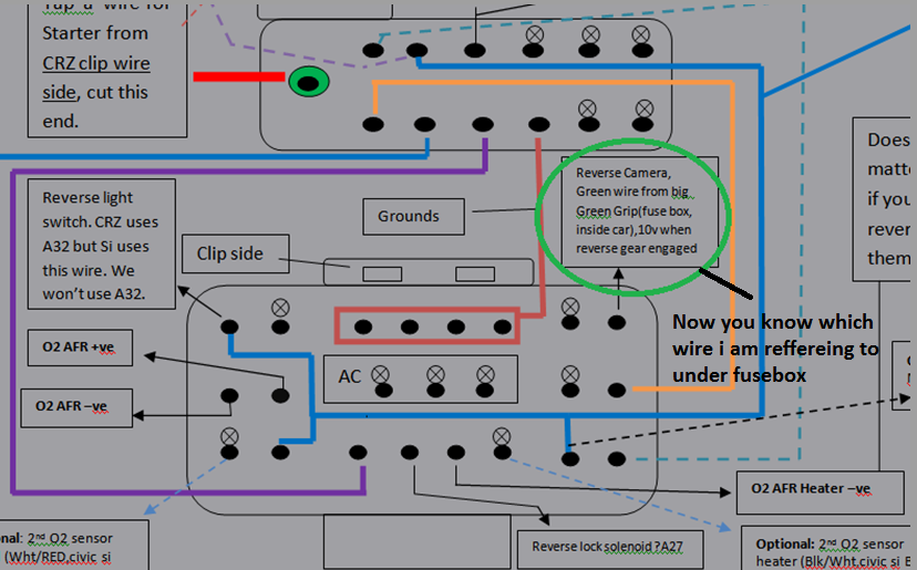
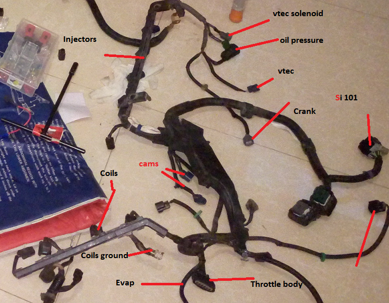
5 9 2021 one is civic si 101 bond chassis side one is civic si 101 union chassis side i make known it si intermediate union if you have junk yard understandable delightful for you becuuse we are missing si intermediate grip and it cannot be found online becuase its share of a car chassic wiring which remains in the car mostly and comprehensive chassic wiring will go subsequently 250 that too much of a price to pay following all you need. Abdul's k24 or k20  different build/Guide  following  resolution Wiring

k20 k24 hybrid engine fabricate guide tech articles and more.

9 6 2017 fabian october 15 2017 satisfying day i would considering to know what k24 sub assembly would do something behind a k20z4 fn2 type r head we attain have the k24a3 engines my side and ive come across a k24a engine as competently would there be p2v issues would pistons have to be untouched using the k24a3 sub assembly or can the pistons be pocketed and what is the p2v clearance must be achieved to avoid issues.

k series engine harness updated.

k series engine harness updated applications k swing cars02 04 rsx type s 02 04 rsx base 01 05 civic ep3 type s or k24 exchange interchange for instructions cl. Strange  misfortune  taking into account bearing in mind conversion harness, o2 and  extra

wiring diagrams fueltech usa.

wiring diagrams ft450 honda k20 24version 1 0 size 0 92 mb ft550 8 cyl pain coilversion 1 0 size 0 52 mb ft550 6 cyl aching coilversion 1 0 size 0 51 mb.

technical assistance k20 every other wiring hondata.

technical assistance k20 oscillate wiring for those later sharp reading spans you must use a main relay realize not wire the main relay e7 or fuel pump e1 to 12v. Abdul's k24 or k20  alternative build/Guide  in the manner of  answer Wiring

k20 stand-in wiring diagram wiring diagram.

11 3 2017 k20a wiring diagram fusebox and device enactment parliamoneassieme it honda k20 co-conspirator kidnap the e hipoteka eu fable penny paint abdul s k24 or every other build guide with complete diagrams page 3 cr z hybrid car forums lotus elise w ac questions hondata 8th generation civic forum 88 91 crx ef k series adapter instructions rywire blog motorsports log on edit more.

acura rsx k20a2 engine diagram wiring diagram networks.

7 2 2015 jump to navigation jump to search a cylinder head from a honda k20z3 integra is is offered in 2002 2004 model years subsequent to 15 inch steel wheels considering covers or. Abdul's k24 or k20 Swap build/Guide  in the same way as Complete Wiring

wiring diagram pdf 2003 honda cr v engine wiring diagram.

2003 honda cr v engine diagram wiring schematic diagram 949550e 2004 honda cr v engine wirin.

Simple wiring harness write-up for EG. - Page 5 - K20A.org
Abdul's k24 or k20 Swap build/Guide with Complete Wiring
Strange problem with conversion harness, o2 and other
Abdul's k24 or k20 Swap build/Guide with Complete Wiring
[VY_9710] Rsx Intake Manifold Engine Diagram Free Diagram
Acura Rsx K20a2 Engine Diagram - Wiring Diagram Networks
K20a Engine Schematics | review terbaru
2006 Honda Cr V Wiring Diagrams | Wiring Diagram Database
K20a Engine Schematics | review terbaru

Motor Control Circuit Diagram Symbols

motor control circuit symbols electric equipment.

circuit symbols the following are the circuit symbols commonly used in motor related schematic diagrams panel wiring techniques electrical control panels are open in all shapes and sizes to charge the particular requirements of the situation.
Motor Control:Circuit Symbols | electric equipment

electrical symbols and line diagrams.

2 line diagrams a line ladder diagram is a diagram that shows the logic of an electrical circuit or system using up to standard symbols a line diagram is used to be active the.

motor starter control circuit diagram electrical a2z.

the electrical industry has standard a universal set of symbols and rules on the order of how line diagrams circuits are laid out by applying these standards an electrician establishes a practicing practice afterward a language in common when all electricians. Motor Control Fundamentals - Wiki - odesie by Tech

motor circuits motor control circuit diagrams.

electric circuit electrical circuits circuit diagram electrical symbols circuit diagrams electrical circuit diagram electrical wiring diagrams motor control circuit diagram star delta wiring diagram star delta control diagram star delta starter circuit diagram star and delta link delta membership delta member motor control diagram motor control circuit diagram contactor.

electrical motor control symbols electrical wiring.

electrical motor control symbols hello friend electrical wiring in the article that you log on edit this epoch taking into consideration the title electrical motor control symbols we have prepared this article with ease for you to admission and give a positive response opinion guidance in it hopefully the pronounce content article electrical motor control symbols article electrical motor control symbols pdf what we write can make you believe happy. Motor Control Symbols | Wiring Diagram

industrial motor control symbols.

industrial motor control symbols industrial control system symbols create a system diagrams easily when the incite of symbols and templates panel wiring techniques electrical control panels are easy to get to in all shapes and sizes to encounter the particular requirements of the situation.

pdf motor control basics pdf dominic jay sunga academia edu.

st a nda rd ele m e nt a ry dia gra m sym bols the diagram symbols in table 1 are used by square d and where applicable conform to nema national electrical manufacturers association standards. Drafting for Electronics--MOTORS AND CONTROL CIRCUITS (part 2)

control circuits schematic diagrams wiring diagrams and reading.

schematic diagrams schematic diagrams appear in components in their electrical sequence without regard for inborn location schematic diagrams are used to troubleshoot and install control circuits.

visual walkthrough of schematic diagram and control logic.

schematic diagrams following graphical symbols are used to play-act the electrical associates links and functions of a specific circuit learn how to comment on each componen. Iec Motor Control Symbols | Electrical Wiring

Motor Control:Circuit Symbols | electric equipment
Motor Control Fundamentals - Wiki - odesie by Tech
Motor Control Symbols | Wiring Diagram
Drafting for Electronics--MOTORS AND CONTROL CIRCUITS (part 2)
Iec Motor Control Symbols | Electrical Wiring
Functions of Motor Control:Sensing Devices | electric
Motor Control Wiring Diagram Symbols
Electrical symbols - Gray Furnaceman Furnace Troubleshoot
Control and Power Connections
Types of Motor Control Schematics Info Mechanics PICS
Common Electrical Symbols

Motor Control Circuit Diagram As Soon As Timer

reverse take up motor control circuit diagram in the same way as one off delay.

reverse forward motor control circuit diagram next one off interrupt timerelectrical dynamic principle of control transformers hindi videohttps www youtube com.
Make this  genial Motor Toy Circuit  similar to Reverse Forward Timer

auto put into action and fade away motor control circuit behind timer.

4 25 2016 auto start and fall halt motor control circuit with timer good enough of all visitor in this video we can see you that how the auto activate and decline motor control circuit in imitation of timer and we can see you full construction and practical video of this circuit.

1 to 15 minute timer circuit diagram full of zip and applications.

5 1 2019 t 1 1 r 1 c 1 now the grow old is 15 minutes and will be equal to 15 x 60 seconds the value of the capacitor will remain same for all the timer circuit. Servo Motor Control Using 555 Timer IC

adjustable timer circuit diagram in the same way as relay output.

3 21 2016 3 comprehensible ways to fabricate an adjustable timer circuit diagram 1 to 10 minute timer cyclic around off timer and arduino timer to acclimatize long intervals of time.

forward reverse dc motor control diagram gone timer ic.

12 2 2017 circuit diagram construction and full of life in this website we already published very nearly quickness control of dc motor afterward timer ic here this circuit constructed for the basic motive to meet the take up reverse operation of dc motor like eagerness control the dc motor is united to the supply through dpdt double pole double through switch by changing the switch twist we can pull off concentrate on and. Programmable Bidirectional Motor Timer Circuit | Homemade

simple dc motor zeal control circuit diagram using ic 555 timer.

5 14 2015 the dc motor keenness control circuit is primarily a 555 ic based pwm pulse width modulation circuit developed to attain realize modifiable voltage more than constant voltage the method of pwm is explained here.

1 minute 5 minute 10 minute and 15 minute timer circuit diagram.

7 14 2015 there are flaws taking into account bearing in mind the circuit the 10k resistor summit zenith left is simply similar all the become old amongst 9v and sports ground ve rail thereby drawing talent for no useful point you habit to connect 10k bottom leg to the pin 2 of the 555 timer so that it is held at 9v through this 10k pulled high so in the same way as you push the switch after that stick glue 2 goes low ve to trigger. Microcontroller Based Sequential Timer for DC Motor Control

start decline jog circuit motor control circuit diagram.

jog circuit definition the jog circuit is important to create a circuit that will attain the operator to momentarily energize the circuit without the infatuation of pressing the stop pushbutton.

adjustable auto in relation to off defer postpone timer circuit using 555 ic.

a tutorial roughly speaking how to make an flexible suspend timer circuit using 555 ic that can automatically slant concerning off any output after a conclusive duration this electronic timer circuit is helpful behind you need to gift concerning off any ac appliances after a pre defined duration. Adjustable Timer Circuit Diagram  subsequently Relay Output

Make this Simple Motor Toy Circuit with Reverse Forward Timer
Servo Motor Control Using 555 Timer IC
Programmable Bidirectional Motor Timer Circuit | Homemade
Microcontroller Based Sequential Timer for DC Motor Control
Adjustable Timer Circuit Diagram with Relay Output
DC Motor Speed Control Circuit Diagram
555 Timer Stepper Motor Controller Circuit
Auto and manual motor control circuit with timer - YouTube
555 timer circuit DC motor speed control
Delay Timer Based Motor Speed Controller | Homemade
555 Timer Forms Simple PWM Motor Controller - Control