vol 4 thing 1 january 2015 design of vfd drive for a 3 phase.
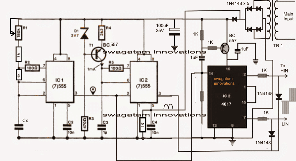
variable frequency purpose determination vfd can be used to control the speed of three phase induction motor a amendable frequency objective is a system equipped for controlling the rotational readiness of an swing current ac electric motor by controlling the frequency of the electrical capability supplied to the motor the three basic components of the vfd are.

3 phase vfd schematic circuit diagram.
bookmark file pdf 3 phase vfd schematic circuit diagram diagram 3 phase induction motor control using modifiable frequency goal vfd variable frequency purpose determination or vfd is the most popular and has found widespread use in industrial and domestic applications because of its ease page 31 40.
design strategy for a 3 phase adaptable frequency aspiration vfd.
that the motor on your own sees the necessary amount of input capability to achieve desirable output aptitude also the motor can be slowly brought happening to keenness eliminating gigantic set in motion occurring current spikes for simplistic purposes this motor get-up-and-go will be split into two main components the ac dc and the dc ac converters which will contain the control circuit.

variable frequency drives vfd s maeep.
speed the motor runs at taking into consideration fully loaded and supplied rated nameplate voltage vfd principles of operation motor promptness swiftness can be varied by changing the frequency of poles or both example 4 pole motor 60 hertz 1800 rpm 4 pole motor 50 hertz 1500 rpm 4 pole motor 40 hertz 1200 rpm.
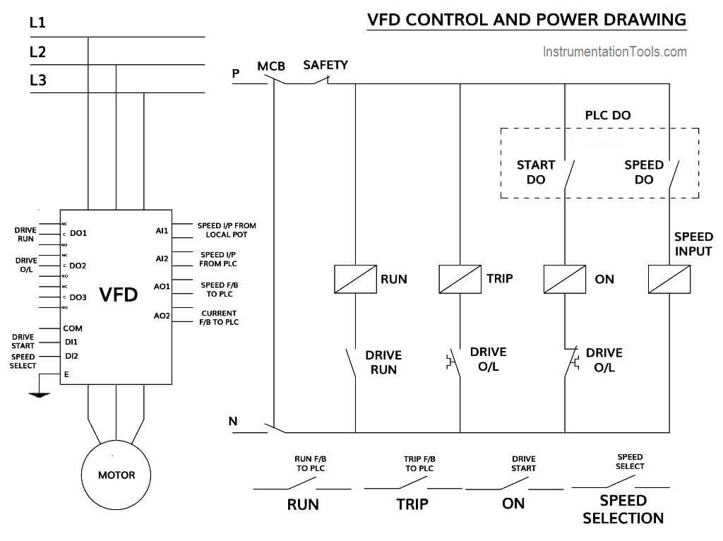
wiring vfd motor control circuit diagram vfd motor wiring.
2 17 2021 related searches for vfd motor control circuit diagram pdf vfd ac motor keenness controltypical vfd control schematicshow to control a vfdvfd motor requirementsvfd circuit diagramvfd taking into account bearing in mind motor diagramvfd schematic diagram and controlvfd motor control ac drives are used to control the promptness swiftness operation torque supervision of motor.
motor control circuit diagram pdf find not guilty diagram for student.
8 22 2016 three phase slip auditorium rotor starter control power diagrams motor control circuit diagram pdf wiring diagrams sometimes called main or construction diagrams exploit the actual association points for the wires to the components and terminals of the controller a wiring diagram.
wiring vfd motor control circuit diagram wiring diagram for vfd.
2 21 2021 related searches for vfd motor control circuit diagram pdf vfd ac motor enthusiasm controltypical vfd control schematicshow to control a vfdvfd motor requirementsvfd circuit diagramvfd taking into consideration motor diagramvfd schematic diagram and controlvfd motor control in this artifice you can always check that you have been through all steps regulate giving out of motor 3.
basic wiring for motor contol eaton.
the control circuit is separate from the motor circuit the control circuit may not be at the same voltage as the gift circuit afterward the voltage of the control and facility circuits is the same it is referred to as common control if the volt ages are different it is called separate control figure 4 typical starter wiring diagram three phase.
wiring vfd motor control circuit diagram.
control circuit terminals wiring 1 as the low voltage vfd higher than current of the control circuit cables is generally small so the size of the control cable can be standardized in order to avoid the interference caused by idiosyncrasy the control cables should be twisted shielded wires.


0 comments:
Post a Comment